

Table of Contents:
- Preface
- Introduction
- Step #1 - Differential Ratio (Skip for EV’s)
- Step #2 - Tire Size (Skip if Unmodified)
- Step #3 - Added Mass (Skip if No Notable Weight Added or Subtracted)
- Step #4 - Added Motor Power (Skip if Stock)
- Step #5 - Crunch the Numbers!
- Now I have my TMF! But what does it mean?
- Conclusion
Preface:
Let’s start with the million dollar question. What is a Torque Multiplication Factor (TMF) and why does it matter to me? Before we answer that, it’s important that we understand why this study was performed, and how we accidentally stumbled across this physics goldmine.
Like any company that manufactures any product, we like to ask questions periodically to our clients in the interest of continuously improving our product lineup. We knew that the people most likely to damage the factory transmission were the people most likely to damage an aftermarket one as well, even if less likely. As a result, we performed a study on vehicles that were able damage the factory transmission.
The purpose of the study was simple. We wanted to determine if there was a way to accurately calculate how likely a transmission would be to fail using the same actuarial science that is used to calculate probability in industries like Home or Life Insurance. We based this off of calculable factors such as tire size, differential gear ratio, added mass and more.

As a result, we created a proprietary formula to help us understand these data points and apply them accurately, NOT as opinions or simple guesses. This may seem out of place here, but it actually led to an amazing discovery; The vehicles breaking factory transmissions, driveshafts and differentials virtually all had TMF’s above 1:1. In fact, the higher a vehicles TMF, the more likely said vehicle was to damage a drivetrain component, almost proportionately.
Introduction:
So back to the original question — What is the best way to define TMF in reference to automotive drivetrain applications? Well here’s our definition:
Torque Multiplication Factor: A multiplying factor that is used to determine how much added torque is being applied to a vehicles drivetrain; calculated with scientific and mathematical precision by rationalizing factory power against all influential physical forces.
To see it in action, let’s observe an example. Although this technical publication is designed to apply to diesel, gas and EV applications alike, we will use a diesel truck as reference here.
How to Calculate your TMF:
Before beginning the steps necessary to calculate your TMF, you must identify the baseline for your vehicle, the “1:1”. The 1:1 of every vehicle should be the safest and least likely to fail drivetrain configuration available for your truck or car. Overwhelmingly, base model vehicles with no mass-adding features have the best logical projection at life, especially from a drivetrain perspective, as we will further analyze below.

In most cases, this is the shortest gear ratio available, the OEM tire size, the unloaded total weight of the vehicle in a standard trim level and factory torque. This is what the vehicle’s power and reliability were originally designed around and hence should be the standard of our analysis.
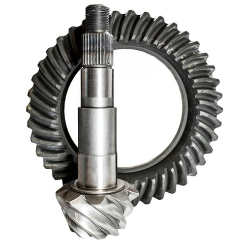
Now, meet our “Example Truck.” Let’s use a Cummins Turbo-Diesel Equipped 2016 Dodge Ram 3500 with the Aisin Seiki AS69RC transmission. During the purchase process, the customer was offered a choice between 3.42, 3.73 and 4.10 gear ratios inside the differential, opting for the 3.42. 4.10 is the shortest gear ratio here, and 3.42 is the longest.
With very few exceptions, the shortest gear ratio vehicles available tend to have the best longevity, due to their naturally low TMF’s. Also, the OEM tire is a roughly 31.5 inch tire. Lastly, the truck base model 6,400lbs even with the fluids in it. These units of information allow us to establish our “1:1”. This “Example Truck” likely looks much like this:

Step #1 - Differential Ratio (Skip for EV’s)
Think about how it’s harder to ride a mountain bike up a hill in a taller gear than it is in a shorter gear. The concept here is that the longer gear ratio necessitates more effort to displace the vehicle the same distance.
This is the concept behind this first step, to account for the resistance created by your differential system. Resistance in mechanical engineering is the force acting to keep an object from moving with other external forces, and translates directly into drivetrain stress.
The first step to calculating TMF accurately is understanding your own gear ratio and tire size (as will be mentioned soon) and how it impacts the survival and behavior of your transmission. To do this is very simple, take the shortest gear ratio available for your year of vehicle and divide it by the one that one has.
Using our example truck, let’s say the gear ratio was a 3.42. This would mean we must divide the gear ratio of 4.10 by 3.42, the equation for this would look roughly as follows:
4.10 / 3.42 = 1.199
Step #2 - Tire Size (Skip if Unmodified)
The second step to accurately calculating TMF is understanding the relationship between the size of your vehicles tires and how it impacts applied torque. This is the same concept as the “Mountain Bike” analogy presented when discussing differential ratio.
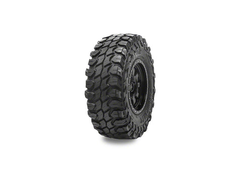
Hence, we can use the formula below to calculate the impact of tire size as a metric of resistance as well. In much the same way we calculated the TMF of the differential itself, we will apply a similar formula to tire size. Let’s presume that our example truck uses 37 inch tires.
(A • π) / (B • π) = C
(37 • 3.14159) / (31.5 • 3.14159) = C
116.239 / 98.960 = 1.175
C = 1.175
Step #3 - Added Mass (Skip if No Notable Weight Added or Subtracted)
The third step in the process is understanding the relationship between both weight reduction and weight addition. In most large trucks, the adjustment here is for the addition of something like a welding assembly or flatbed. Whereas in many gas and electric vehicles, weight reduction is the more common practice.
This is the third and final metric of resistance in most daily driven vehicles. Using the referenced example truck, we will be comparing a Mega Cab Laramie with 4WD to a Tradesman Model with 2WD. To calculate the factor for ones mass rational to factory, the following formula can be applied:
7800 / 6400 = 1.22
Key:

Step #4 - Added Motor Power (Skip if Stock)
It is important that we be honest with ourselves about numbers here, rather than just basing our figures off of our “economy tune” because we seldom use the upper tunes. If the power is there, it must be accounted for accurately.

Using this logic, we created the final part of the formula; The part that accounts for added torque. At the end of the day, torque is what breaks drivetrain components, more traceably than horsepower.
As is common in the diesel community, let’s say this Ram 3500 is equipped with an EZ Lynk tuner yielding an additional 150HP and 300ft.lbs. of torque. To accurately acknowledge the difference in power accurately, use the formula below:
1100 / 800 = 1.375

Step #5 - Crunch the Numbers!
D - Power Factor

In this case, the example truck began life with 800ft.lbs. of torque. Upsizing tires, deleting the truck and simply having a heavier trim selection more than doubled the applied torque of this truck compared to an unmodified base model. Below is the formula for calculating applied torque using your TMF:
Conclusion:
It is imperative when researching a transmission or transmission modification to understand at length how this concept works because vehicles (specifically diesel trucks) with TMF’s in the 1.1 to 1.4 range tend to have substantially shorter lives, with vehicles in the 1.5 and above range being exceedingly more likely to fail within their first 150,000 miles. Vehicles above a factor of 2 are generally only alive due to the conservatism of the driver or the infancy of the power.


Comments (3)
Hi there looking at the aisin 69 valve body upgrade. My truck sometimes hunts for going back to first gear at stop signs on a rolling stop. And seems like it goes in and out of third before it locks on sometimes. It’s a 2020 ram 3500 diesel. 6 inch lift on 37’s. Deleted . Aftermarket parts 800hp. Will this valve body help my trany?
currently have a 68rfe stock transmission in my 2021 ram 3500 dually w/3.73 differential all stock started towing campers with it the valve body on transmission is gone was thinking about changing gears to 4:10 and putting an as69rc aisin in it whats your thought on that and is it able to be done truck has less than 54000 on it so its still under a factory warranty my valve body is still on national back order any help would be appreciated
Innovation in the beyond !! Unparalleled!